Denker's Mini Lathe Page
Mini Lathe
Information
I
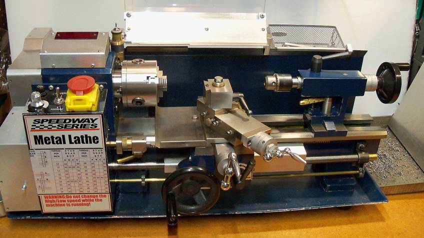
purchased the old version of the HOMIER 7" x 12" mini lathe. It comes
with 4mm change gear keyways and a number of other differences from most other
mini lathes. I don't think they make these anymore so unless you buy one of
these used, you will get 3mm gear keyways with most of the parts the same
between makers. Now the main differences are color, metric or inch cross-slide
screw and compound rest screw and the length of the machine. The motor has
plenty of power for this machine size but the drive gearing is a bit high for
most threading and large diameter machining. Also the plastic drive gears may
be a little light duty. As a result, I greatly modified my lathe.
Updated Dec. 2020
Modification
Contents:
![]() Gear
Plate Change (Updated)
Gear
Plate Change (Updated)
![]() Cross
Slide Lock (New!)
Cross
Slide Lock (New!)
![]() Other
Additions & Changes (Updated)
Other
Additions & Changes (Updated)
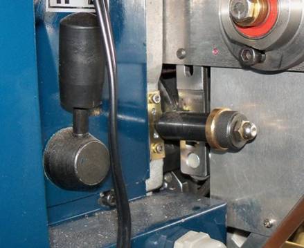
Machine Stop Addition
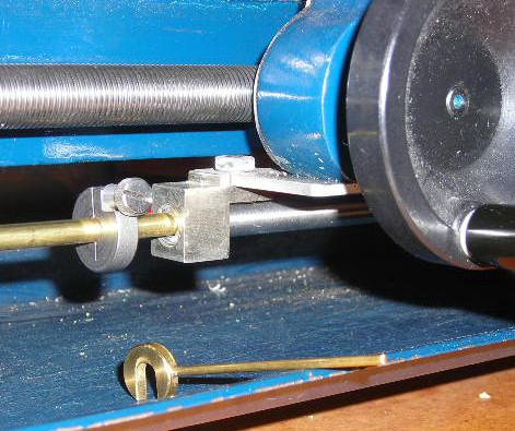
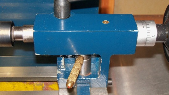
This
addition is mainly used during threading operations to stop the machine at the
end of the threads. I usually cut a groove where the threads end so there is
room for some variation where the cutter stops. A set ring on a rod below the
lead screw is set so it is hit by an addition to the carriage assembly. This
rod can move in either direction and activates a switch inside the control
cover to turn off the lathe. The carriage must be moved away from the stop
before the motor can be turned on again. It can also be used as a safety stop.
METRIC THREADING NOTE! When doing metric threads with a non-metric lead screw,
do NOT disengage the lead screw because threading will not match again. This is
a problem because when the switch is open the motor cannot be started. For
metric treads I add a spacer (shown in picture) on the stop rod for each
cutting pass. When the machine stops I remove it, (the switch closes) then I
back off the cutter and reverse the lathe back to the start of the thread. This
is quite a hassle but is the only way it can be done without changing the lead
screw to a metric one. (which I think would also be a hassle!) I don't do many
metric threads so I'll keep using the inch one.
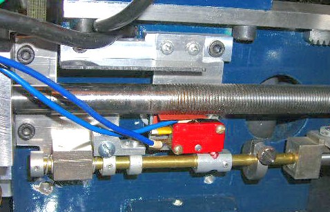
The next picture shows the switch with
the controller removed.
Low Speed Addition
This
addition lowers the spindle speed limit to about 600 RPM and almost doubles the
torque. This is a major addition with many parts and I use it most of the time.
It completely bypasses the internal plastic gears. (The speed selector must be
in neutral) Low speed can be disabled to use the higher speeds when needed. The
method I used reverses the direction of the spindle so on this machine a switch
must be added to reverse the half speed function. (Note: Other makers of this
lathe may not have a reverse half speed function.) This is a nice addition for
the additional power needed when machining bigger parts and for the lower
speeds needed when threading, grooving or cutting off parts.
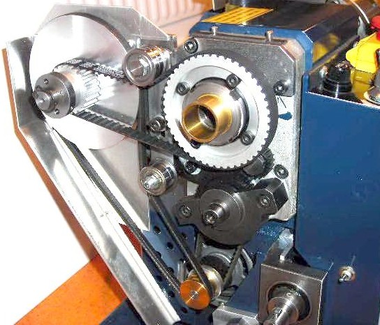
This addition and others required big
changes to the gear cover. Always have the gear
cover on when operating the lathe!
Note: This
cover has now been replaced. (see New Gear Cover)
Gear Plate Change
I
greatly disliked the original change gear plate. It was hard to adjust and
required adjustment every time a change was made. Adjustment was centered on
the lead screw shaft when it should be on the "A" shaft. So after a
lot of engineering, out with the old and in with the new! This 0.25" thick
plate was laser cut at work and has many built in gear options. The gear plate
mounting shaft and the "A" shaft mount had to be slightly modified too.
(Note: My "A" shaft mount is bigger than most other manufacturers.)
With the addition of 21, 25 and 42-tooth gears, I can make just about any
metric thread to within 0.00015" per inch. (For threads within the machine
capability limits using plastic gears) For inch threads, I can get many threads
by changing only the lead screw shaft gear and adjusting the gear plate. Also
this configuration gives me many more machining feed possibilities. (Down to
0.0018"/rev with the added 25T gear.) I use 8mm x 20mm long shoulder bolts
with spacers to hold the gears to the plate. There is also a T-nut held in
place with a thin spring steel bracket for gear adjustments. (No need to get a
wrench behind this thing!)
ENGINEERING NOTE: Because this plate uses some machined in gear
mounting locations, it does require good machining location on the
"A" shaft and good quality gears! The gears center hole should be
straight for minimum wobble and centered within 0.005". It may be
necessary to design in additional length between gear locations if the gears
are not of good quality. If you do not want to use machined in mounting
locations, there is room for two T-nuts in the middle slot. That would give you
gear adjustment for most gear placements. I have inch setup and metric setup charts using only the
slot.
Now that the gear plate does not
rotate on the left lead screw mount, I can improve wear and performance by
replacing it with a ball bearing mount.
Note: Because this plate can have more
gear locations, it may not maintain a direction standard. Some gear setups may require
using the reverse of the normal feed selection. This setup is for a M0.7
thread. (To be more accurate: M0.70009)
Many
of my setups use additional gears. I have found getting gears and modifying
them for this machine quit easy and inexpensive. (My machine uses 4mm keyways.)
I have also designed a metric lead screw version of this plate for metric threads but will not make one.
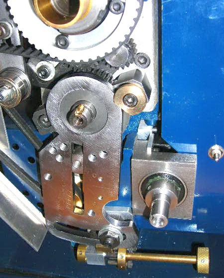
GEAR PLATE UPDATE:
After a long time of use, I have found
that the gear plate could be improved. Here is what the new improved version
looks like.
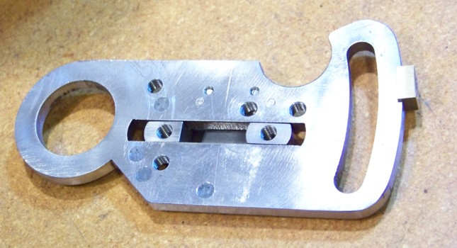
Notice
the slot now has two adjustable mounting T-nuts and I removed some machined in gear
locations and added a new one. By using the multiple gear plate addition (next
picture), I can now get multiple feed rates and many
thread setups changing only the lead screw gear. Here is a drawing of this gear plate.
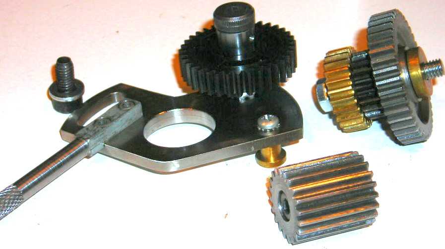
Multiple Gear Plate
Addition
OK
- on this one I got a little carried away! With this addition I can get 3 different
machining feeds by changing a gear location. The 35-tooth gear mounted on the
plate of the next picture uses a spring and ball indent so it can be moved. I
can get most standard inch and many other threading feeds by changing only the
lead screw gear and the position of the gear plates. I don't think it's going
to get much easier on this machine. I did have to buy and modify more gears. I
recommend using metal gears whenever possible and I have switched over to all
metal gears. I have also added a 12mm ID x 21mm OD x 5mm ball bearing to the
"A" shaft in its mount and a bronze bushing in the aluminum belt
cover for the 7mm end of the shaft. (Required modifying the "A" shaft
,its mount and the belt cover. Also note my "A" shaft mount appears
to be bigger than most other machine manufacturers and they may not have room
for a ball bearing.) I made a steel 20-tooth 3 deep (0.95" long) gear from
a purchased gear blank to use on that shaft. For machining, the 3-gear cluster
is made up of 25, 20 and 40-tooth gears with the 20 or 40-tooth used to drive
the next gear. These 3 gears are connected by a key on the modified brass
25-tooth gear. It looks like too many gears, but everything works well. I use
this addition most of the time but I do remove it for metric threads. Using
other gearing possibilities, this addition gives me a very wide range of
machining feeds. NOTE: This addition also required
modifying the gear cover for gear clearance.
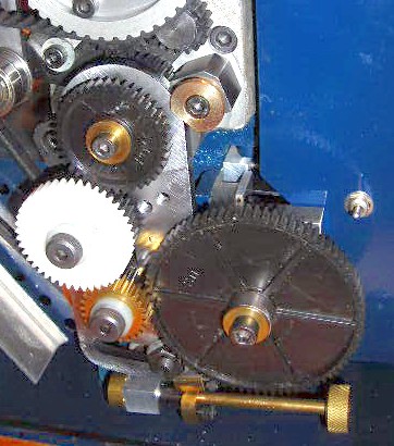
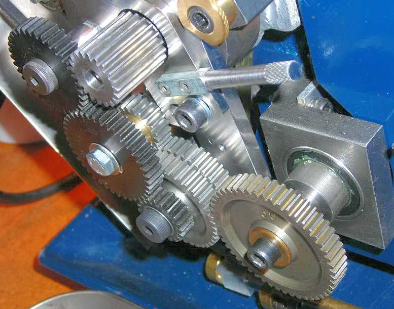
The next picture shows the setup for machining feeds. The 20-tooth gear of the cluster is
used to drive the middle 80-tooth gear.
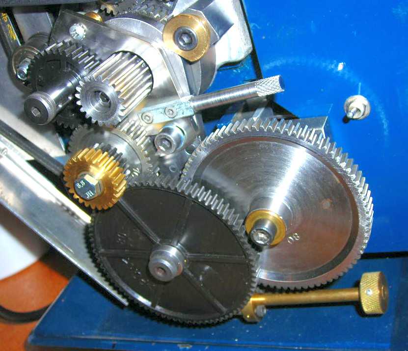
The
selection knob below the gear plate is used to setup for different machining
ranges so changes can be made easier and faster. Adjustment screws are used to
preset the location of the gear plate for a 20, 25 or 30-tooth gear on the
inside of the middle 80-tooth gear. This gives me 9 machining selections from
0.0020"/rev to 0.0059"/rev. I have removed the middle 80-tooth gear
on the next picture to show it better. The knob is turned to select one of the
three adjustment screws or none at all. The knob position is held by a ball and
spring indent. NOTE:
with my new GEAR PLATE UPDATE, I no longer use this.
This
gear plate can also be used for threading. I am now able to thread 28 inch
sizes from 7 to 104TPI using one plate setup by changing the location of the
movable 35-tooth gear and the location of the lead screw gear. I can do that
using 4 threading groups. The 3-gear cluster is now made up of a 40-tooth, a
gear spacer and a 20-tooth gear keyed together on a bushing. The clusters
40-tooth then drives a 20-tooth keyed to a 40-tooth and the clusters 20-tooth
drives a 40-tooth on its own bushing and not keyed to the next 40-tooth. The
inside 40-tooth gear turns at 1/4th the speed of the outside
40-tooth gear. One of these gears is then used to drive the lead screw gear.
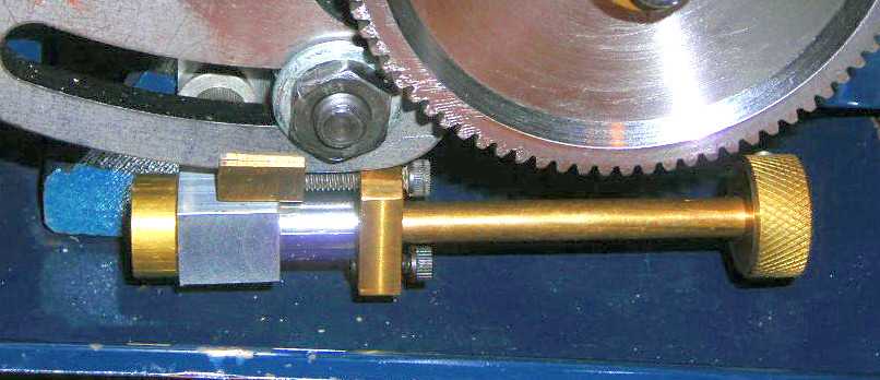
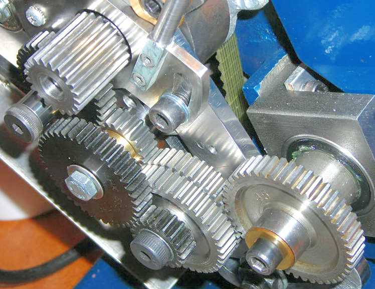
The next picture shows one of these setups. The 14 to 26TPI group is shown with
the 50-tooth gear (20TPI) on the lead screw shaft using the outside position.
If the 50-tooth gear was on the inside, it would be setup for 80TPI of the 56
to 104TPI group.
The
setup in the next picture is for the 28 to 48TPI group with the 45-tooth gear
(36TPI) on the lead screw shaft using the inside position. If the 45-tooth gear
was on the outside, it would be setup for 9TPI of the 7 to 13TPI group. I have
a drawing showing these inch thread group setups for this plate addition. I do not recommend
threading under 14TPI on this machine without the low speed addition and the addition
of ball bearings on the "A" shaft and the lead screw shaft. I would
also recommend converting to metal gears. For the overall capabilities of this
lathe, the gear plate additions and the low speed addition are big improvements
and greatly increases the value of this machine to me. Even though it required
quite a bit of work, I am very happy with both!
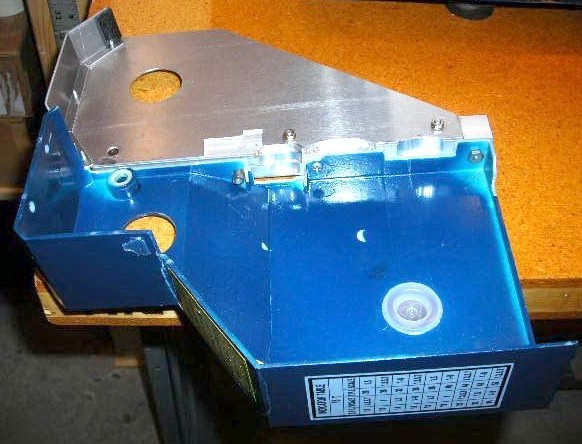
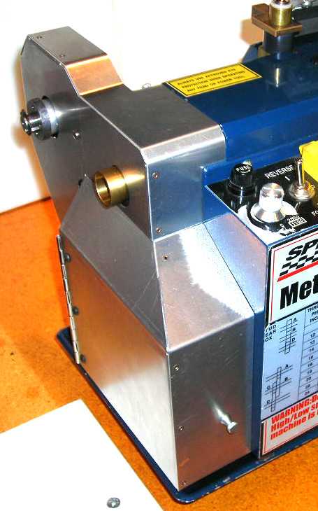
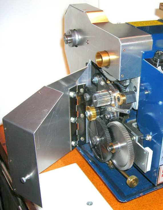
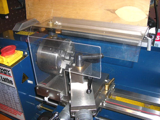
New Gear Cover
As
of Dec. 2008 I replaced the old gear cover with a new one made just to fit the
low speed and gearing changes. The original cover has always been slow and
awkward to take off and put on. Especially with the low speed addition. This
new one is much easier and faster to open and gives me more room for the
additional gears of the gearing changes. It has a hinged door so the rest of
the cover can be better attached and has a magnetic latch. The next 2 pictures
show it on the lathe. It was made using 0.050" and 0.062" think
aluminum. Next I am going to order blue paint so it will match the rest of the
lathe.
Tailstock Change
The
tailstock had 2 things that needed changing. The first thing is the nut to bolt
it down. It’s a pain in the neck. There are a few kits available to fix this
but I went with a lift and set adjusting nut. The inside bed surface of my
machine is not very parallel with the top so some of the available methods
would not work well. I couldn't find an adjustable lift handle that fit in the
tailstock cavity so I made this one. It is easy to adjust and can be moved out
of the way in either direction when done.
The
second change I wanted was a gauge dial on the tailstock screw shaft. This was
not possible with the metric threads being used. I needed something with 20 TPI
or a M1.0 thread. I drilled out the old quill thread with a 0.390"
diameter drill and tapped it 7/16 - 20 left hand. After making a new tailstock
screw shaft, buying an inch style 50-division compound rest dial, compound rest
retainer and making the other necessary modifications, I was almost done. My
lathe did not come with depth markings on the quill so I added them too.
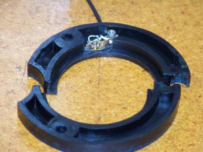
Spindle Tachometer
I
wanted to add a tachometer to the lathe but with the changes made to the gearing,
there was no place to put an interrupter wheel or sensor. The only place left
was the chuck side of the gear housing. At that location an interrupter wheel
was out so I was going to have to bounce a light beam off the spindle itself. I
had some old infrared LED's and sensors from an old computer card reader, so I
made a sensor bracket out of 0.020" brass shim stock and soldered these on
it. After some testing I was reasonably sure it would work so I designed the
rest of the project and got started. The only good place for a sensor was
inside the plastic bearing cover but I could not get the cover off unless I
took the spindle off! As a result I decided to cut the cover in two. I used a
hot knife to cut it at the top mounting hole and at the bottom. After cleaning
up the hot knife cuts, it now comes off and mounts back on easily and it did
not look bad. I milled a spot for the sensor on the back side of the cover and
ground a notch in the gear housing to run the wire out the back of the lathe. I
did not want the sensor wire anywhere where metal chips could get at it. This
will plug into the display housing using a 3.5mm stereo audio plug. The next
pictures show the finished sensor assembled on the bearing cover.
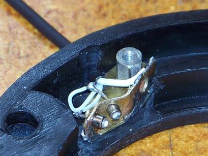
Next
I painted 6 marks about 0.20" wide using flat black paint evenly spaced on
the spindle. For 6 marks, the display has to have a 1 second update rate. I
also have the option of using 12 marks at a half second update rate, but 1
second seems to work nicely.
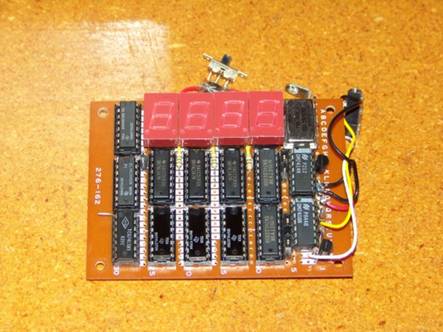
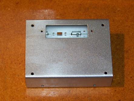
The next pictures shows the finished
display board and housing which was made of 0.050 aluminum and painted.
And here it is assembled and running
on the lathe.
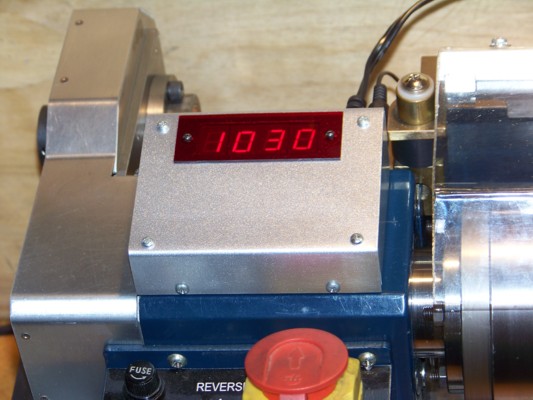
This project turned out quite nice. It
displays RPM to the nearest 10 +or-10. The power supply is a 5.5V regulated
wall plug unit so no power supply parts were needed in the box.
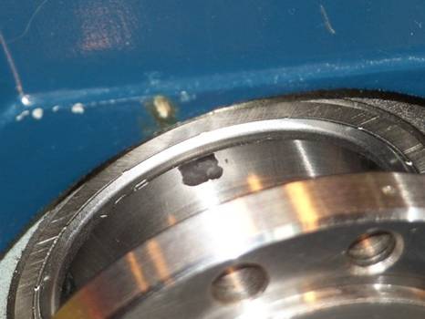
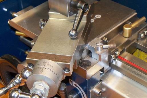
Cross Slide Lock
For
a long time I have often had chatter problems with some cutting operations.
Also sometimes some of my more aggressive tools would catch and gouge into the
material. (this would stop the motor) I always thought it was because of the
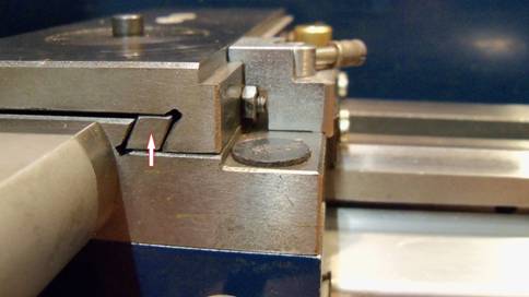
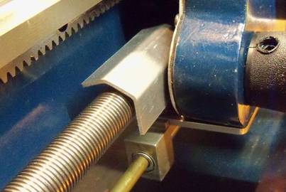
lathe's small size. The problem was not what I expected! The right side of the cross slide would rise
up when a tool catches. The cross slide gib would
rotate in place when this happens. (see next picture arrow) With everything
adjusted correctly, I could manually lift up on the compound rest and get a
0.007" feeler gauge between the cross slide and the carriage. (just right
of the arrow) This is a design problem on multiple levels and not easy to fix.
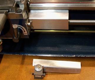
So I decided to fix the effect instead of the cause. First I milled out a
0.14" x 0.14" step on the right side of the cross slide. Then I added
a cross slide lock (clamp) where it would hold down the right side even when
the lock is not used.
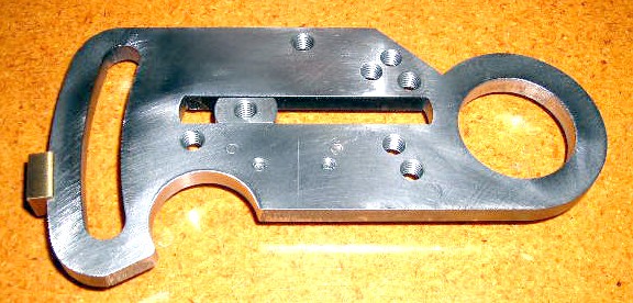
Both
pictures shows the finished lock. It was made from 0.75" square steel
stock and is 0.87" long. It is low enough so it does not interfere with
the compound rest.
The
results of this addition have been very good. When not using the lock I move
its lever until it just hits resistance. This helps hold the cross slide down
with no upward movement during normal use. That has greatly improved the
cutting quality of cutoff tools, boring
bars, chamfer tools and others. I can now take more material off during normal
operations with greatly reduced chatter problems. For those who use a milling
fixture on the lathe, this would improve that too. I rank this in the top 3 of
my improvements for cut quality on the lathe. The other 2 are the lower speed
addition and adding the holes necessary to move the compound rest back on the
cross slide (which is related to this problem).
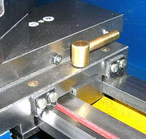
Other Lathe Additions
& Changes:
![]() With the addition of the low speed
modification, I found it harder to pull out and move the feed engagement and
direction lever. So I cut off the gear shifter handle to about 0.50" long
and pressed on a 0.875" diameter brass ring to it. Now it is much easier.
Also added a steel set plate which is better than the aluminum surface it used
before.
With the addition of the low speed
modification, I found it harder to pull out and move the feed engagement and
direction lever. So I cut off the gear shifter handle to about 0.50" long
and pressed on a 0.875" diameter brass ring to it. Now it is much easier.
Also added a steel set plate which is better than the aluminum surface it used
before.
(Updated Oct. 2020)
![]() This lathe does not come with a
carriage lock. My lathe has a different carriage design then most others and
that made it easy to add one. This is the lock I am using.
This lathe does not come with a
carriage lock. My lathe has a different carriage design then most others and
that made it easy to add one. This is the lock I am using.
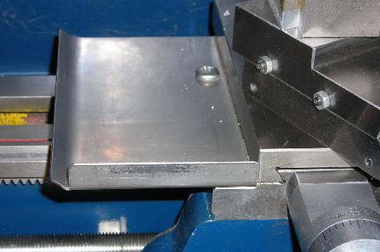
![]() I added a chip pan on the carriage and
a shield that clamps to it. This one is made from 0.050" SST. I have
several chip pans of different sizes for different chucks. This helps keep most
of the metal chips off the wear surfaces and the lead screw. It also adds a
place to attach a chip guard.
I added a chip pan on the carriage and
a shield that clamps to it. This one is made from 0.050" SST. I have
several chip pans of different sizes for different chucks. This helps keep most
of the metal chips off the wear surfaces and the lead screw. It also adds a
place to attach a chip guard.
![]() To increase the range of the
cross-slide and compound rest, I added spacers to both. The above picture shows
the cross slide one. (0.35" thick) The next picture shows the other.
(0.50" thick)
To increase the range of the
cross-slide and compound rest, I added spacers to both. The above picture shows
the cross slide one. (0.35" thick) The next picture shows the other.
(0.50" thick)
![]() It is also a good idea to add some
chip shields. The next picture shows what I am using. The top one has an
extension and moves out of the way if necessary. I have also added a kill
switch to this for the times I need to use one and an override switch on it for
the times I don't. The other shield attaches to the added carriage chip pan.
It is also a good idea to add some
chip shields. The next picture shows what I am using. The top one has an
extension and moves out of the way if necessary. I have also added a kill
switch to this for the times I need to use one and an override switch on it for
the times I don't. The other shield attaches to the added carriage chip pan.
![]() (new) I added chip guards for the lead screw
on both sides of the half nuts. I have found over time the bottom half nut gets
a buildup of small chips that interfere with its operation and is quite a bit
of work to clean. These help keep it clean. The one on the left goes under the
rack pinion all the way over to the half nuts. (4-1/2" long) I get full
use of the carriage with these on. The right side has 2 different ones, with or
without the threading indicator.
(new) I added chip guards for the lead screw
on both sides of the half nuts. I have found over time the bottom half nut gets
a buildup of small chips that interfere with its operation and is quite a bit
of work to clean. These help keep it clean. The one on the left goes under the
rack pinion all the way over to the half nuts. (4-1/2" long) I get full
use of the carriage with these on. The right side has 2 different ones, with or
without the threading indicator.
![]() I added an extension to the spindle so
metal chips would not fall into the gears. (See the Low Speed Addition picture) Note: The gear end cover should always be on when operating the
lathe.
I added an extension to the spindle so
metal chips would not fall into the gears. (See the Low Speed Addition picture) Note: The gear end cover should always be on when operating the
lathe.
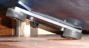
![]() It is also a must to widen the spacing
of the feet on the bottom of the lathe for better stability. This is easy to do
by adding an easy to make bar.
It is also a must to widen the spacing
of the feet on the bottom of the lathe for better stability. This is easy to do
by adding an easy to make bar.
All pictures and
content Copyright © 2007, 2008, 2012, 2020, 2021 David Denker.
All Rights Reserved.
Last Revised: Feb.
2021