Denker's Mini Mill PAGE
Home
Built Mini Mill Information
My
mill is a combination of purchased mini mill assemblies and other purchased and
fabricated parts. The head assembly (R8) and column are standard mini mill with
a purchased compound mill table mounted on a 1/2" thick steel base.
Everything is greatly modified. The column does not rotate on the base like the
standard machine, but is held vertical by 0.25" thick supports and a
4" webbed iron angle plate. Instead of the standard head support spring or
gas support system, I am using a counterbalance. (far better) I went with a
different table because I wanted something a bit heavier and 0.100" per
rev. dials. I used a standard 5" x 8" PHASE II table and modified it.
For the most part it came out very well but I would recommend using a large
U-beam for a base instead of a flat plate. My plate required extra supports.
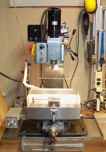
(Updated picture as of Oct. 2020)
Modification Contents:
![]() Z-Axis
Control (Changed)
Z-Axis
Control (Changed)
![]() Other
Additions & Changes (Changed)
Other
Additions & Changes (Changed)
Compound
Table
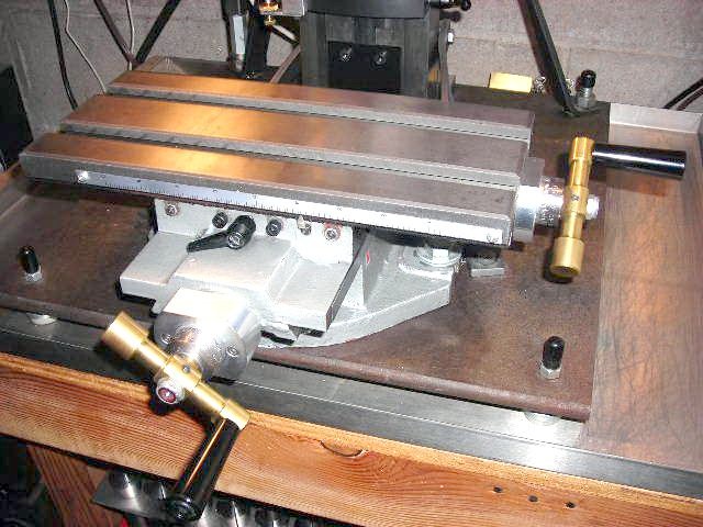
The
mill table I bought was a little on the ruff side. I paid about $70 for it and
it showed. The acme screws had between 0.010" and 0.015" of backlash
and the handles were too small. It came with the X-axis handle on the left so I
switched it to the right side. To remove some of the backlash, I added thrust
bearings and made new longer acme screw shafts to accommodate the extra length
of the thrust bearing housing. (Also added length for a power feed unit) As
long as I was doing that, I made new acme nut brackets too. Now the backlash is
under 0.005". It would be better if I used better acme nuts or bought a
1/2-10 acme tap and made my own. I also had to add X and Y-axis lock handles
(this table did not come with them) and added inch scales. Finally I replaced
the 2.5" handles with 3.5" brass ones to get an easier feel. Overall
this was quite a bit of work for a heavier duty table. Was it worth it? - I
think so. To get 0.100" per rev. feed, there are not many low priced
options out there. For a heavy duty table it is well designed, milling chips do
not get anywhere they shouldn't and is just about the right size. After the
improvements, I would say it has been very good.
Counterweight
From
what I have read and seen on the Internet, the mill head support systems used
on the standard mini mills are not very good. I decided to go with a
counterweight system instead. I mounted a 4" pulley on top of the column
and a 10" THOMSON linear bearing bar (surplus) on the back for the
weights. I connected the head to the weights with a plastic covered steel
cable. The motor controller box had to be mounted on the left side of the
column. It works great but adds major weight to the machine.
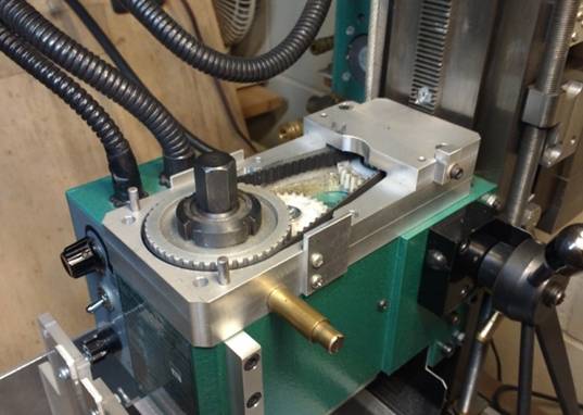
Low Speed
Addition
This
is a big project that required a large amount of engineering and just as much machining.
It gives the machine a 0 to 700 RPM speed range with 1.5 times the output
torque. It also bypasses the internal plastic gears. The motor is mounted on a
position plate so it can be moved forward or back. To engage the low speed
range, I move the motor to the rear position where it engages a different gear.
This system reverses the spindle direction so a reverse switch must also be
added. This is not a easy addition but it sure is worth it. I can now use
bigger drills and mills and with the reverse switch I can use it for tapping
without a big tap head. The housing is made of 1/2" thick aluminum plates
layered 3 high and bolted and pinned together. It uses the same timing belt
system as the low speed addition of my mini lathe but with a gear instead of
the V-belt. I changed the gear on the motor from a 16-tooth to a 15-tooth so
the higher speeds are now 0 to 1040 RPM and 0 to 2380 RPM.
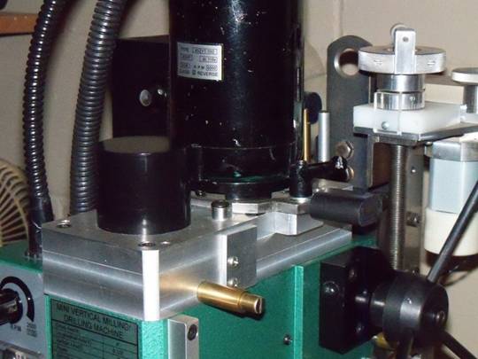
This housing also has a spring-loaded
spindle lock pin. (Updated Oct 2020)
Table
Power Feed
This
is not an easy project and required considerable engineering. The housing is a
3" x 3" x 0.125" thick square aluminum tube that encloses the
switches, relays, gearing and bearings needed for the drive. I'm using a 30VDC
motor that draws about 1 amp and has a motor overload protection circuit set at
about 1.5 amps. It also has stop switches for adjustable position stops located
behind the compound table. There is an engagement lever to engage the X-axis
acme screw because a worm gear is used in the design and the X-axis cannot be
moved by hand with the power feed engaged. The maximum feed rate of this system
is about 8" per minute. A separate box located behind the mill houses a
power transformer, circuit breaker for the unit, SCR controller board and Hi/Lo
feed speed switch.
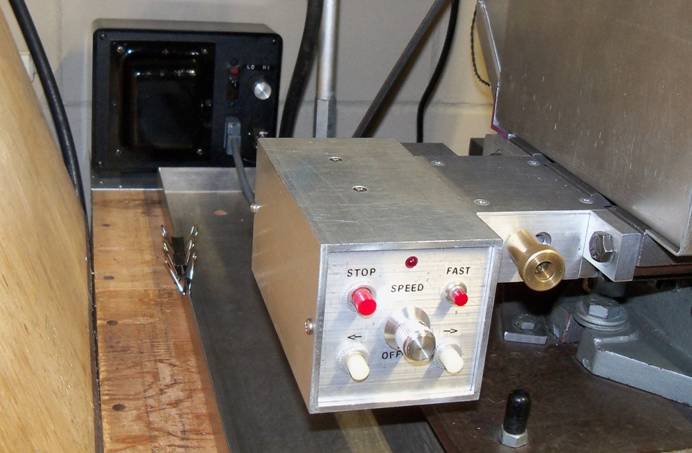
(Updated Jan 2021)
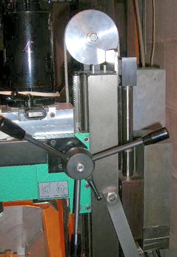
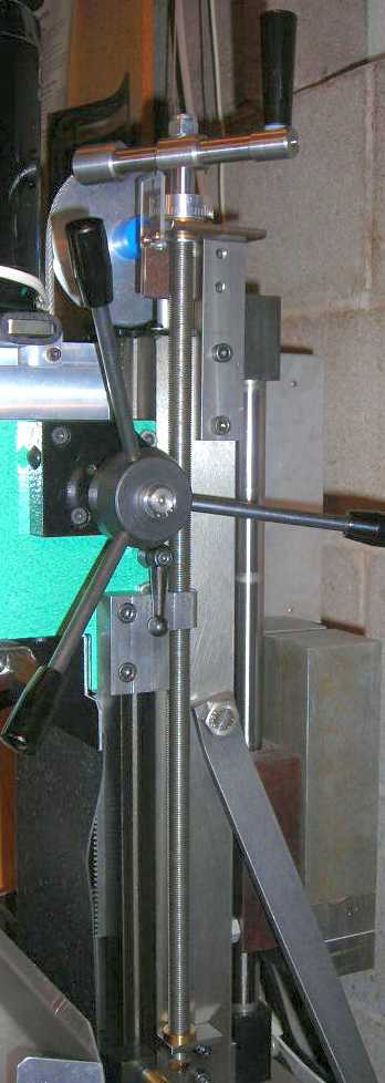
Z-Axis
Control:
I
have found z-axis head control can be a little tricky for some operations.
Because the hand and fine feed controls use a gear and rack, which has a bit of
slop, operations like drilling out large holes, boring and vertical milling can
be a problem. To make this easier I added a z-axis screw. Others have done this
and I found it helpful too. For normal operation, I remove the two bolts from
the screw head bracket and rotate it 180° to the back. (Shown just under the
head locking lever) I am using a 1/2"-20 threaded rod so each turn moves
the head 0.050". The purchased rod I used is not dimensionally accurate
and is off by about 0.040" in 10 inches. I would have to make my own screw
if this was not good enough in the future. With this now in place, I removed
the old fine feed system.
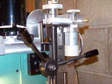
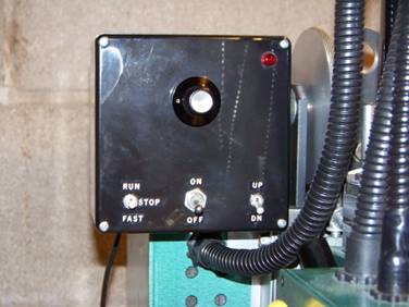
Now I have added a Z-Drive motor with
its gearbox and a control box. The motor was salvaged from an old paper
shredder and the control box uses a variable transformer for speed control. The
gear box is hinged so it can be disconnected from the lead screw. I also added
Top and Bottom limit switches with the bottom one movable. This works great
when using a Boring Bar Head.
Other
Mill Additions & Changes:
![]() It is an absolute must to have a
Z-axis indicator. This one uses an addition to the mill stop bracket to engage
a 1" travel indicator mounted to the mill head. I have a 1" and
2" spacer that can be added when setting it up to get longer movements.
(up to 4" total)
It is an absolute must to have a
Z-axis indicator. This one uses an addition to the mill stop bracket to engage
a 1" travel indicator mounted to the mill head. I have a 1" and
2" spacer that can be added when setting it up to get longer movements.
(up to 4" total)
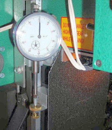
![]() In the above picture you can also see
an added column chip guard. It is a thin rubber mat cut to about 5.5" x
12" with weight added on the bottom and mounted to the mill head. It's cut
just long enough to protect the wear surfaces. As the head moves down, it folds
in place.
In the above picture you can also see
an added column chip guard. It is a thin rubber mat cut to about 5.5" x
12" with weight added on the bottom and mounted to the mill head. It's cut
just long enough to protect the wear surfaces. As the head moves down, it folds
in place.
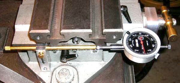
![]() Another addition that is very nice at
times is a X and Y-axis indicator. This takes the guesswork out of the backlash
of the table. For less wear on the indicators, I only mount them when needed.
(This is the Y-axis one.) I have not added any DRO's because the good ones cost
so much and I haven't really needed them. (Maybe in the future?)
Another addition that is very nice at
times is a X and Y-axis indicator. This takes the guesswork out of the backlash
of the table. For less wear on the indicators, I only mount them when needed.
(This is the Y-axis one.) I have not added any DRO's because the good ones cost
so much and I haven't really needed them. (Maybe in the future?)
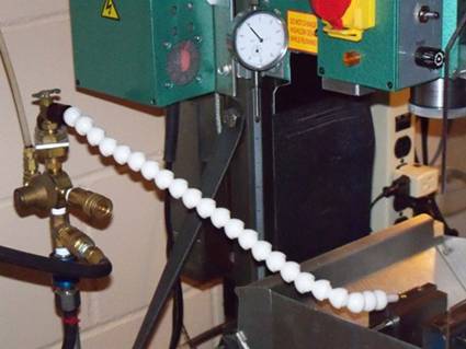
![]() I have a small air compressor in my
shop and have air blow off brackets and nozzle that can be mounted on the mill.
I have also added a flexible air nozzle on the left side of the mill.
I have a small air compressor in my
shop and have air blow off brackets and nozzle that can be mounted on the mill.
I have also added a flexible air nozzle on the left side of the mill.
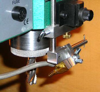
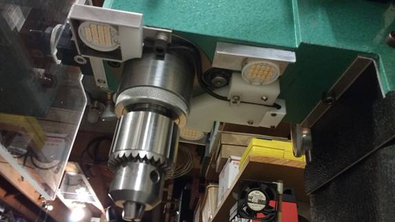
![]() I have redone the lighting on the mill
head using LEDs. This is a much cleaner and brighter system. I am using 3
120VAC LED modules that are hooked into the mill control box for power. I
replaced the green light in front with a switch so I can turn these off when
needed. (when using a laser center)
I have redone the lighting on the mill
head using LEDs. This is a much cleaner and brighter system. I am using 3
120VAC LED modules that are hooked into the mill control box for power. I
replaced the green light in front with a switch so I can turn these off when
needed. (when using a laser center)
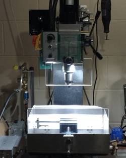
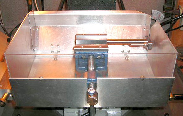
![]() This is a chip containment box I have
mounted on the compound table. It is easily removed with 6 thumbnuts when
milling large parts or for long parts, ether side can be replaced with a
shorter version. With it and the mills stock shield, I can contain over 95% of
the metal chips in the box. It sure makes cleanup easier!
This is a chip containment box I have
mounted on the compound table. It is easily removed with 6 thumbnuts when
milling large parts or for long parts, ether side can be replaced with a
shorter version. With it and the mills stock shield, I can contain over 95% of
the metal chips in the box. It sure makes cleanup easier!
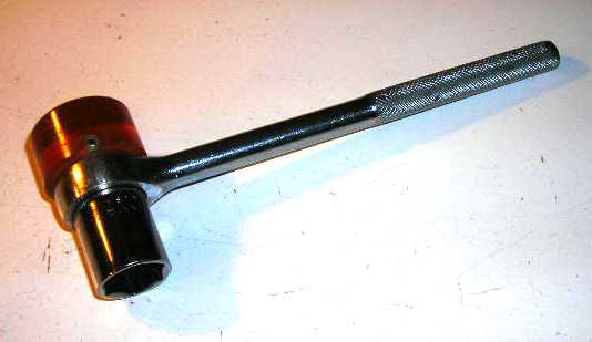
![]() This is my drawbar wrench and mallet.
It was made from an old broken 3/8" ratcheting socket wrench and an 18mm
socket. Also added was a 1 3/8" dia. plastic mallet end.
This is my drawbar wrench and mallet.
It was made from an old broken 3/8" ratcheting socket wrench and an 18mm
socket. Also added was a 1 3/8" dia. plastic mallet end.
All pictures and
content Copyright © 2007, 2008, 2009, 2020, 2021 David Denker.
All Rights Reserved.
Last Revised: Feb.
2021